← All knowledge guidesKNX/EIB Standard

KNX Cable Installation Requirements

Professional guide to KNX/EIB bus cable routing and installation. Technical requirements, standards and best practices for reliable building automation.

Core installation requirements

Following these requirements ensures reliable and long-lasting operation of your KNX system.

Maximum line length

No more than 1000 metres per line

  • Total length of all segments ≤ 1000 m
  • Distance between two devices ≤ 700 m
  • Distance from power supply to device ≤ 350 m

Electrical isolation

Separation from power cables

  • Minimum 4 mm from 230V power cables
  • Use separate cable ducts
  • Crossings only at 90° angle

EMC protection

Shielding and grounding

  • Ground cable shield on one side only
  • Avoid parallel routing with power lines
  • Use certified KNX cable

Operating conditions

Temperature and humidity

  • Operating temperature: -5°C to +45°C
  • Humidity: up to 93% non-condensing
  • IP20 protection for indoor installation

Prohibited

  • Do not route KNX cable in the same duct as power cables
  • Do not use ordinary twisted-pair cable instead of certified KNX cable
  • Ring topologies within a line are strictly forbidden

Best practices

  • Use colour coding: red (+), black (−)
  • Leave cable slack in junction boxes
  • Document all connections and topology
  • Check polarity before connecting devices
Virasmart — Ekinex KNX partner

Technical specifications

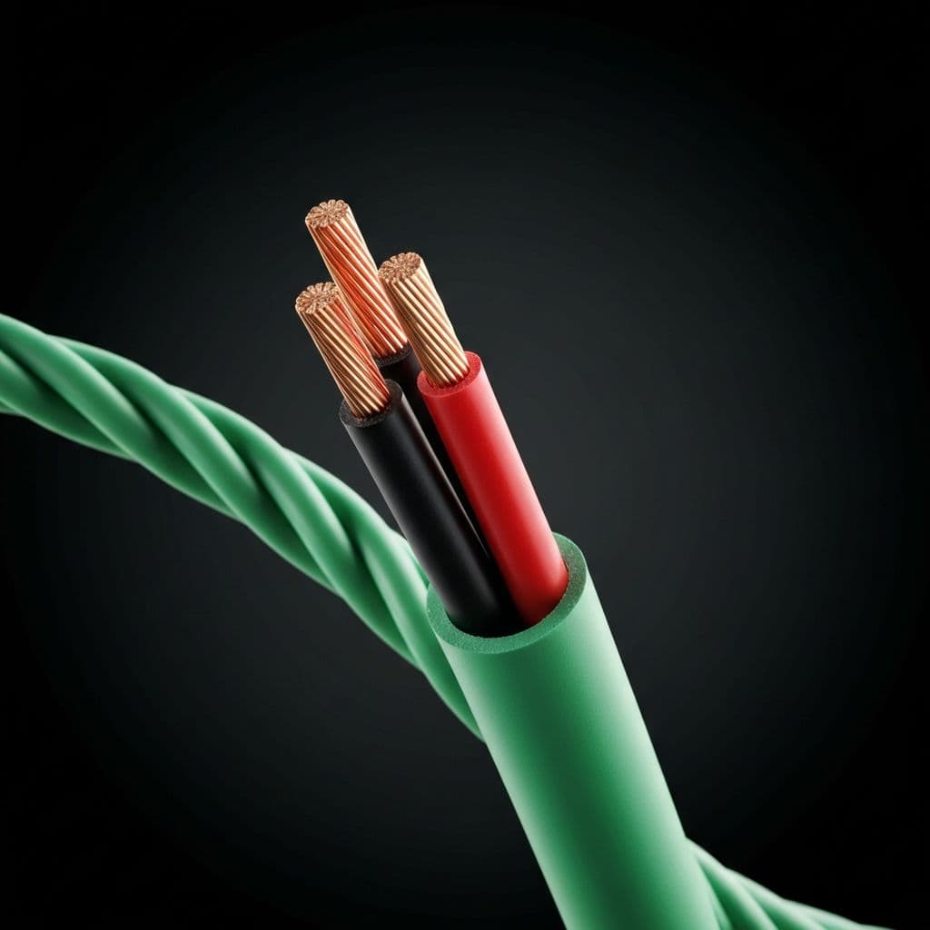
Detailed cable characteristics and KNX/EIB system parameters.

Cable types

Standard

YCYM 2x2x0.8

Primary cable for indoor installation

  • Cores2 × 2 × 0.8 mm
  • Outer diameter5.0 mm
  • Resistance≤ 73 Ω/km
  • Insulation voltage300 / 500 V
  • ShieldNone
RecommendedShielded

J-Y(St)Y 2x2x0.8

For installation in high-interference environments

  • Cores2 × 2 × 0.8 mm
  • Outer diameter6.0 mm
  • Resistance≤ 73 Ω/km
  • Insulation voltage300 / 500 V
  • ShieldAluminium foil

Topology limits

Devices per line64pcs
Lines per area15pcs
Areas in system15pcs
Devices in system57 600max

Electrical parameters

Bus voltage29V DC21–32V
Current consumption10 mAtypical
Data rate9600bit/s
Access methodCSMA/CA

Wire colour coding

Red+UB (positive)
Black−UB (negative)
YellowReserve / SELV
WhiteReserve / SELV

Supported topologies

KNX supports free topology without closed loops.

Line

Devices connected in series

Advantages

  • Simple installation
  • Minimal cable use

Disadvantages

  • Break affects entire line

Star

All devices connected to a central point

Advantages

  • Device independence
  • Easy diagnostics

Disadvantages

  • More cable required

Tree

Combination of line and star topology

Advantages

  • Flexibility
  • Optimal cable use

Disadvantages

  • More complex planning

Important: ring topology is prohibited

Ring connections (closed loops) are strictly forbidden in KNX. They cause telegram collisions and system failures. Always verify the absence of closed loops before commissioning.

Need help with a KNX project?

Our engineers design, install and commission KNX systems across the Baltics. Submit a brief and we will respond within one business day.