KNX Topology Explained
Lines, areas, segments and couplers — how a KNX network is structured, how far it scales, and the design rules that keep large installations stable.
Every reliable KNX installation starts with a sound topology. KNX is a decentralised bus where devices communicate as equals, but the way you group them into lines and areas — and where you place couplers and power supplies — determines how far the system scales, how fast it responds, and how easy it is to extend years later. This guide explains the building blocks and the rules that matter on real projects.
The building blocks: device, line, area
KNX is organised in a clear three-level hierarchy.
At the lowest level sits the bus device — a sensor, actuator or controller with a unique individual address. Up to 64 devices share a single line segment, the smallest functional unit of a KNX network.
Lines are grouped into an area, and areas connect to a backbone. This hierarchy — device → line → area → backbone — is what lets KNX scale from a single apartment to an entire commercial building on one logical network.
- Device — one bus participant with a unique individual address (e.g. 1.1.5)
- Line — up to 64 devices, fed by its own power supply
- Area — up to 15 lines joined by line couplers
- Backbone — up to 15 areas joined by area couplers
| Devices per line segment | 64 |
| Segments per line (with repeaters) | 4 |
| Lines per area | 15 |
| Areas per installation | 15 |
With line repeaters a single line can carry up to four segments of 64 devices — but every repeater adds telegram delay, so plan capacity rather than relying on repeaters as an afterthought.

Line and area couplers
Couplers join the hierarchy and, crucially, filter traffic.
A line coupler connects a line to the main line of its area; an area coupler connects an area to the backbone. Physically they are the same device used in different positions.
Couplers do more than connect — they filter telegrams. A correctly configured coupler only forwards traffic that needs to cross the boundary, keeping local bus load low. This filtering is the single biggest reason large KNX networks stay responsive.
- Line coupler — line ↔ main line of an area
- Area coupler — area ↔ backbone
- Filter tables forward only the group telegrams that must cross
- Galvanic isolation between coupled lines contains faults
Enable filtering in ETS once commissioning is complete. The 'pass all' setting is useful for diagnostics but cripples bus performance if left on in production.
Individual addresses vs group addresses
Two address types do two very different jobs.
The individual (physical) address — area.line.device, e.g. 1.1.5 — uniquely identifies each device and mirrors the topology. It is used for programming and diagnostics, never for normal operation.
Group addresses carry the actual functions: a light switch and the actuator it controls share a group address. Group addresses are independent of topology, which is exactly what lets one button control devices anywhere on the network.
- Individual address — topology-bound, used for download and diagnostics
- Group address — function-bound, used for runtime communication
- A clean group-address structure (main/middle/sub) keeps large projects maintainable
Power supplies and distance limits
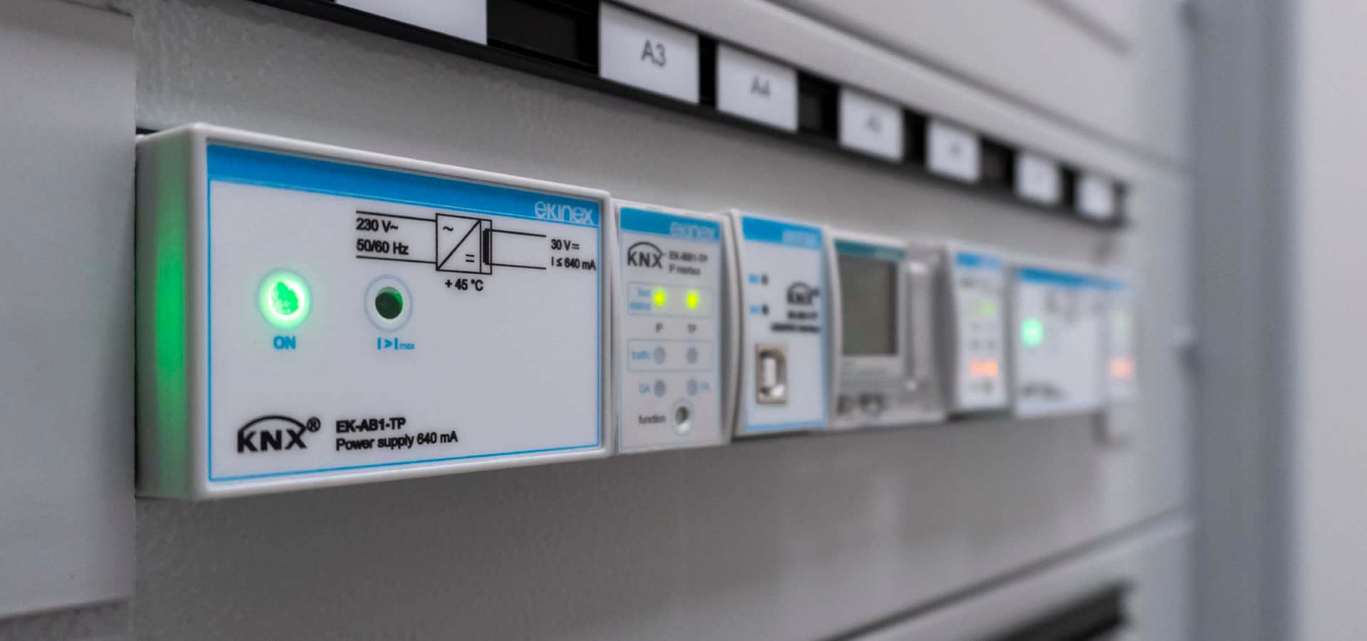
Every line segment needs its own KNX power supply.
A KNX power supply provides the 30 V DC bus voltage together with the choke that lets data and power share one twisted pair. Each line segment requires its own supply; you cannot feed two segments from one supply across a coupler.
Size the supply to the number of devices and their bus-current draw, and respect the maximum cable distances between the supply and the most distant device.
- One power supply per line segment (typically 320 mA or 640 mA)
- ≤ 350 m from power supply to any device
- ≤ 700 m between any two devices on a line
- ≤ 1000 m total bus cable per line
| Bus voltage | 30 V DC (min 29 V at device) |
| Supply to device | ≤ 350 m |
| Device to device | ≤ 700 m |
| Total cable per line | ≤ 1000 m |
These distance limits are covered in detail in our KNX cable installation guide — topology design and cabling go hand in hand.
Design rules for scalable installations
A few habits keep KNX projects healthy as they grow.
Good topology is about leaving room to grow and keeping bus load low. Reserve spare capacity on every line, group devices by physical proximity, and align your line structure with the building's electrical distribution.
Document the topology in ETS exactly as installed. The next engineer — possibly years later — will rely on it, and a topology that mirrors reality is the difference between a ten-minute fault find and a half-day.
- Fill lines to about 80% and leave headroom for additions
- Group devices per distribution board and per floor
- Keep couplers' filter tables enabled in production
- Use one consistent group-address scheme across the whole project
- Separate critical functions onto their own lines where practical
Planning a larger KNX project in the Baltics? Virasmart's engineers design the full topology, ETS structure and commissioning plan — talk to us before the first cable is pulled.
Designing a KNX network?
From topology and ETS structure to commissioning, Virasmart engineers KNX systems for residential and commercial projects across the Baltics.